Styrofoam IFS - Getting started
Theory
IFS fractals are defined by a number of transforms, a transform consists of a number of math-formulas.
Traditionally a transform looks like this, one function for x and one for y:
x1 = a*x0 + b*y0 + e
y1 = c*x0 + d*y0 + f
Where a,b,c,d,e and f are selected differently for each transform.
In other words, take a position in space, defined by (x0,y0), and use a transform to get a new position (x1,y1).
Depending on which transform gets selected, the position will change to different new positions.
To draw the fractal, start at position (0,0).
- Select one of the transforms at random.
- Apply the transform to the current position to get a new position.
- Draw a pixel at the new position.
- Repeat for a while. The number of times this is repeated is called iterations.
Since Styrofoam IFS works in three dimensions, it puts a sphere at the new position instead of a pixel and raytraces all spheres after the fractal has been calculated.
Creating the first fractal
Create a new text file in Notepad (or your text-editor of choice).
Type in the following in the file:
xform
translate 0.0001,0,0
Then save the file as first.ifs in the ifs directory in the StyrofoamIFS folder.
Create another text file, let it be empty and save it as first.scene in the same folder.
Keep both of these files open in separate editors, we will be changing them quite a bit.
Start StyrofoamIFS.
Select first.ifs in the IFS dropdown and select first.scene in the Scene dropdown.
Use the mouse and click on the dropdown menus. They will only be updated with new files when clicked.
If you still can't find them, you have probably put the files in the wrong folder.
Click Render IFS.
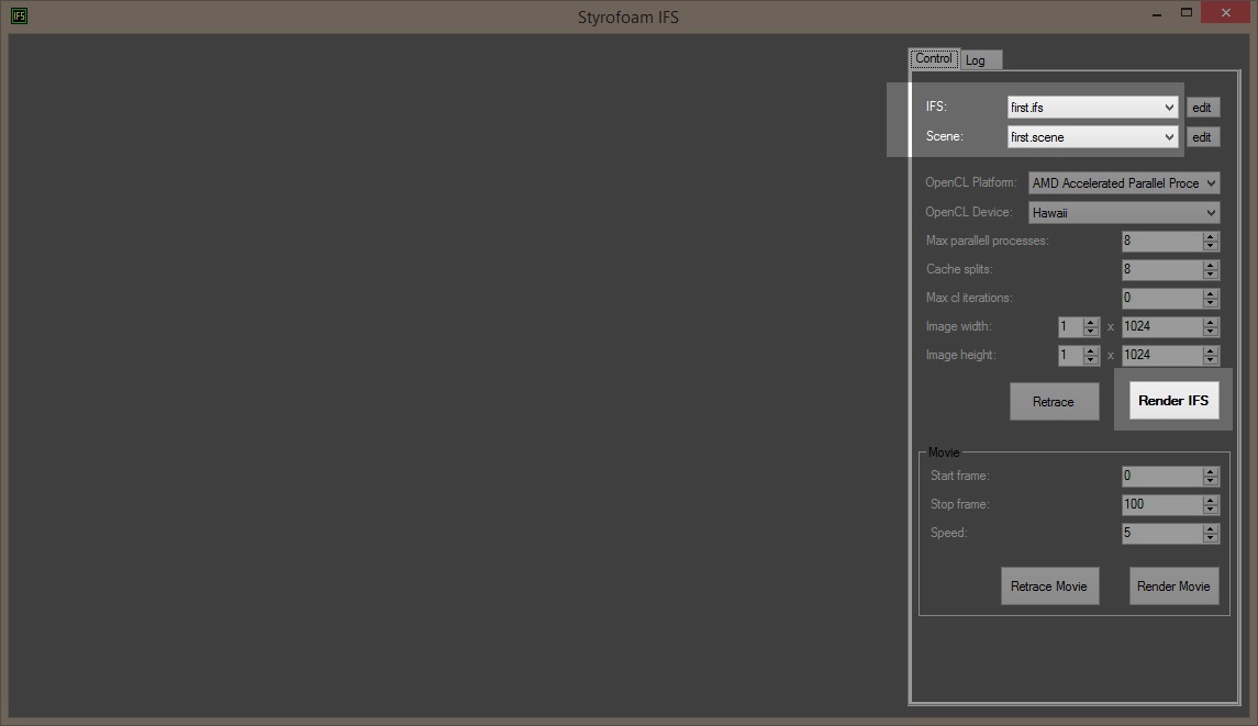
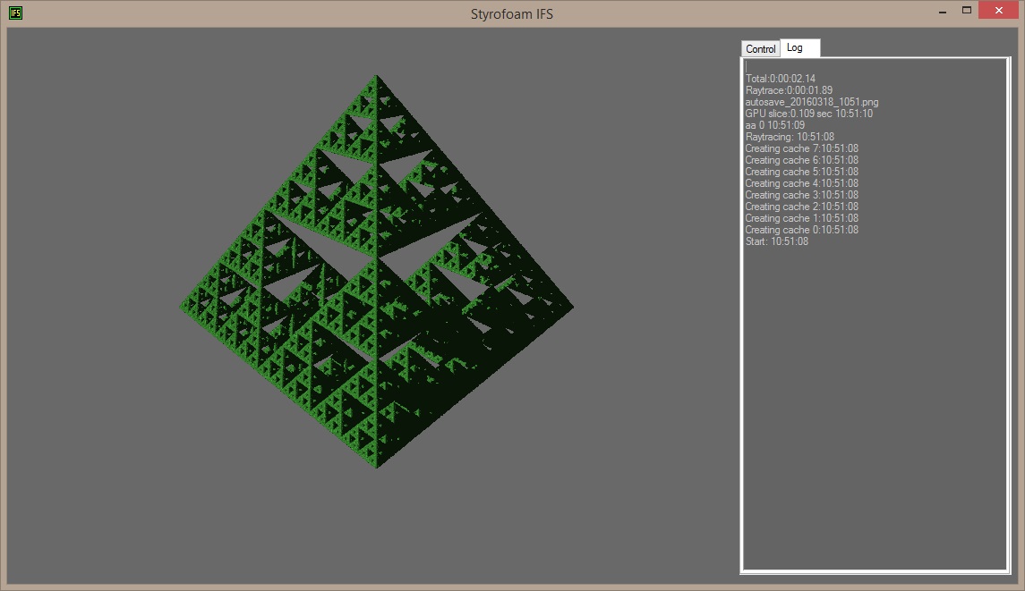
Note that the other values may not be the same on your system as shown here.
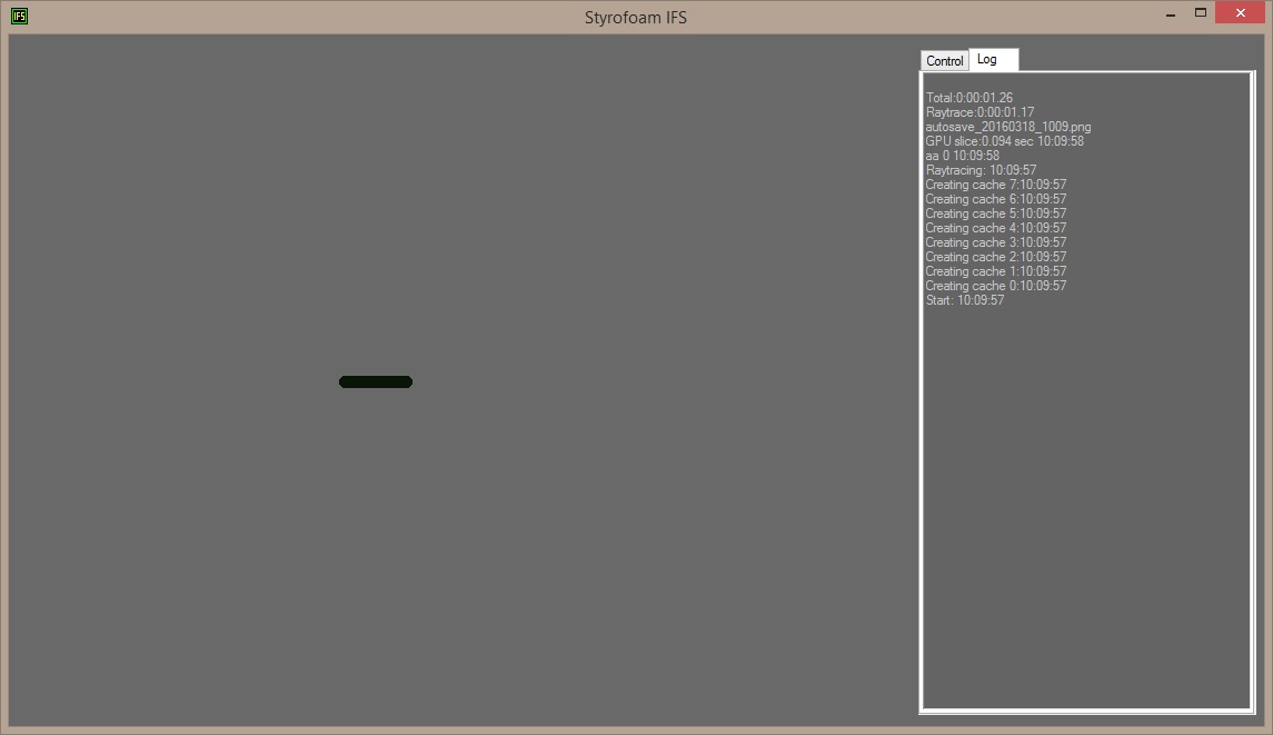
The program will switch to Log tab automatically while rendering to show its progress.
All transforms must start with a xform command. It means that a new transform-definition will start here.
The translate command corresponds to an addition formula to the current transform. It is the only formula in this transform.
In this case the transform will end up like:
x1 = x0+0.0001
y1 = y0+0
z1 = z0+0
We have only defined one transform here so it will be selected every iteration.
Starting at (0,0,0) the first new position will be (0.0001,0,0)
Then (0.0002,0,0), (0.0003,0,0) and so on.
First there's an initial 1000 iterations without drawing any sphere.
The starting position might not be part of the final fractal and this lets the fractal move around a bit before any drawing is made.
After these initial iterations the postition is at (0.1,0,0).
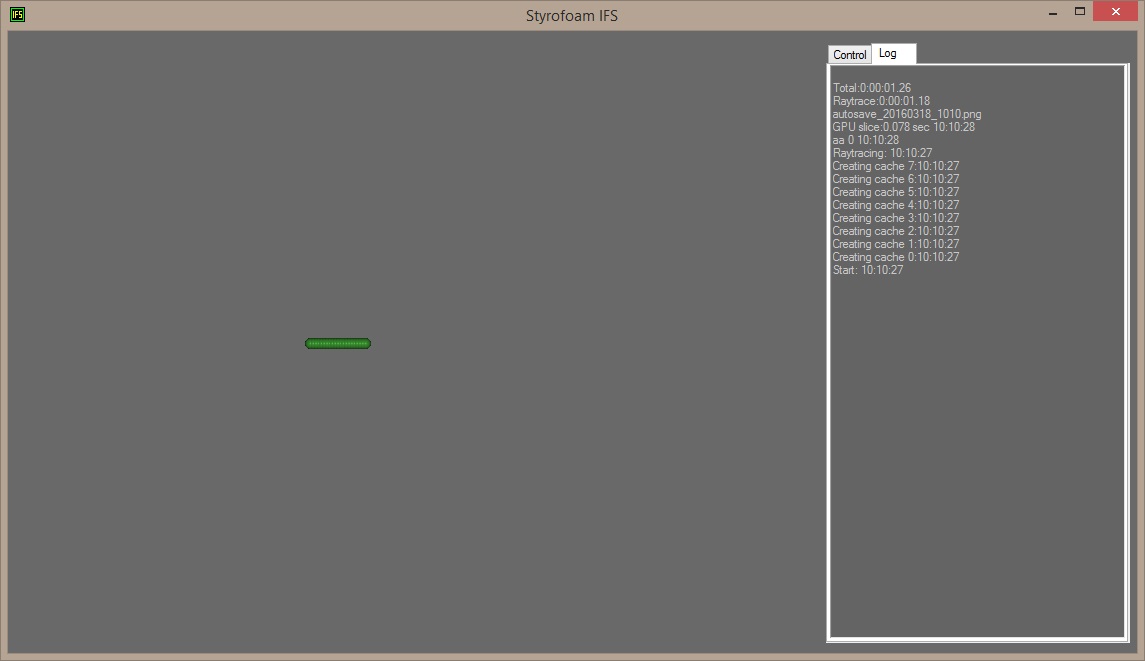
Next the normal iterations will start where a sphere will be drawn after each transform.
By default the number of iterations are 1000 so 1000 spheres will be drawn from position (0.1,0,0) to (0.2,0,0).
Don't mind that there aren't actually 1000 spheres in the image right now, this will be explained later.
To see the spheres instead of just dark shadows we need to add light to the image.
Switch to the .scene file (which was left empty earlier) and add the following row:
lightsource 0,0,-1
This will put a lightsource at position (0,0,-1) and light up the spheres.
Save the file, go back to StyrofoamIFS, switch back to the Control tab and click Render IFS again.
You can add several lightsources to an image just by adding more lightsource rows.
Next we are going to add more transforms.
Open up the first.ifs file and replace the text there with the following:
xform
scale 0.5,0.5,0.5
translate 0.2,0,0
xform
scale 0.5,0.5,0.5
translate -0.2,0,0
xform
scale 0.5,0.5,0.5
translate 0,0.25,0
Each xform starts a new transform consisting of the formulas after.
The scale commands corresponds to an multiplication to the current transform.
The first transform will look like:
x1= 0.5*x0 + 0.2
y1 = 0.5*y0 + 0
z1= 0.5*z0 + 0
The second transform will be:
x1 = 0.5*x0 - 0.2
y1 = 0.5*y0 + 0
z1 = 0.5*z0 + 0
And the third:
x1 = 0.5*x0 + 0
y1 = 0.5*y0 + 0.25
z1 = 0.5*z0 + 0
Save the file, go back to StyrofoamIFS, switch back to the Control tab and click Render IFS again.
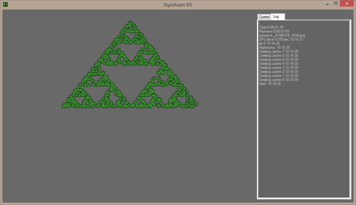
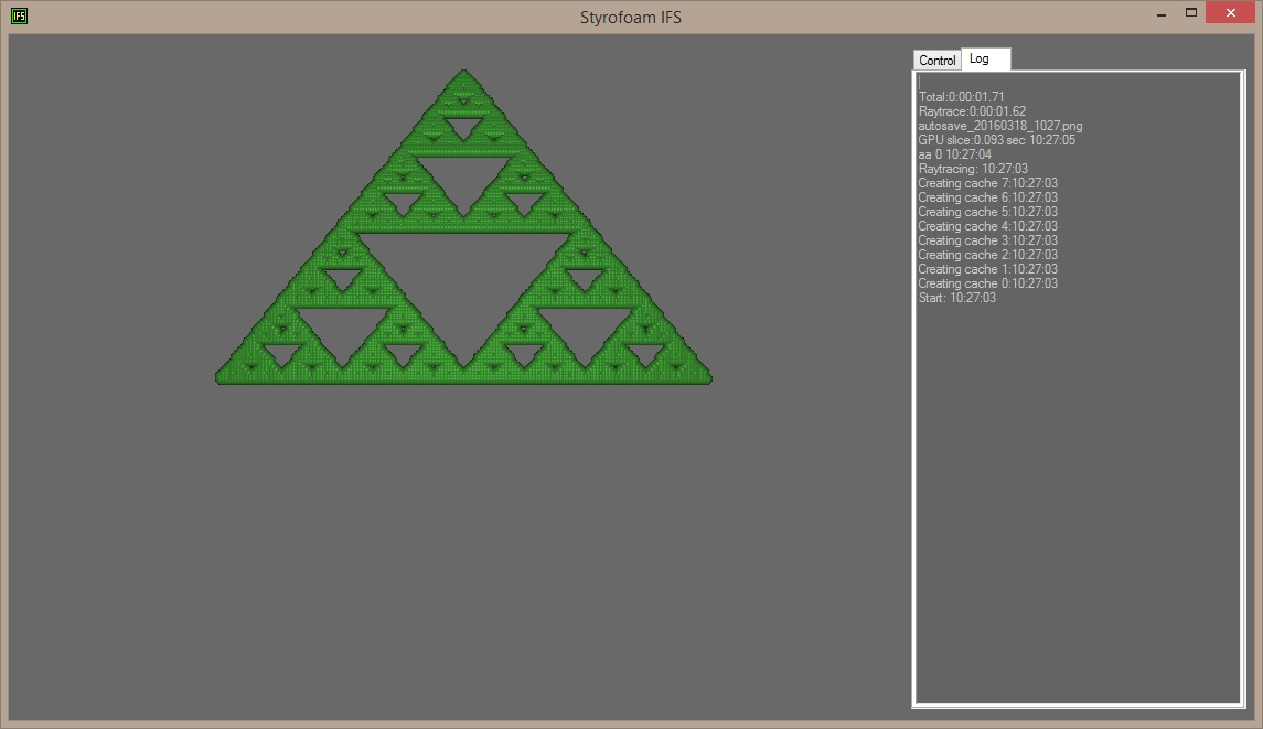
The program will randomly select one of the three transforms, apply it to the current position in space and draw a sphere.
You can see the form of a Sierpinski triangle emerging but with only 1000 iterations it looks unfinished.
Open the .scene file and add a new row after the lightsource row:
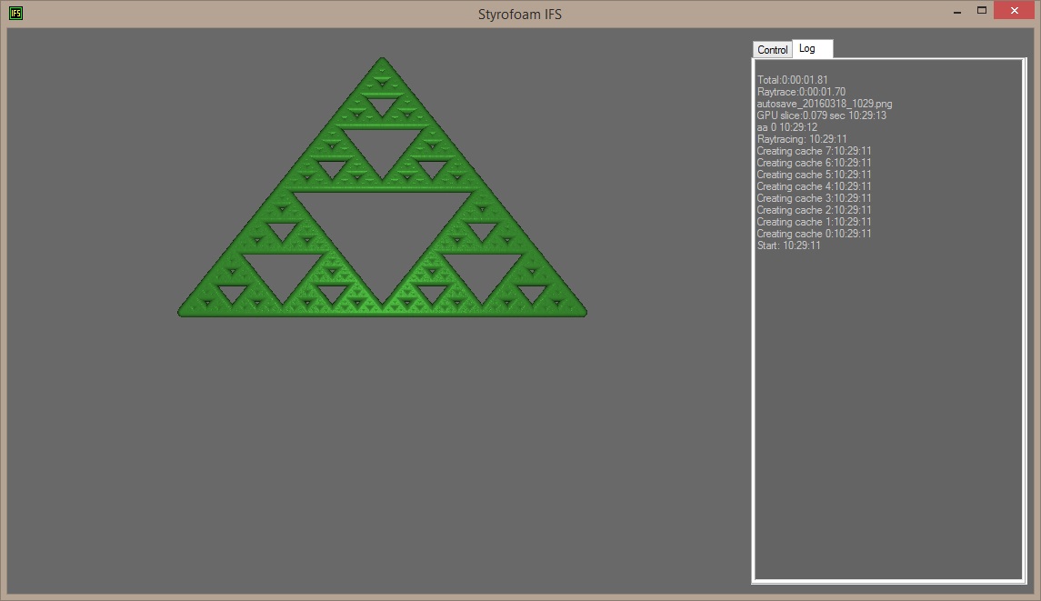
iterations 100000
This changes the number of times a transformation is applied and a sphere is drawn to 100000.
Save the file, go back to StyrofoamIFS, switch back to the Control tab and click Render IFS again.
If you look closely on the image you see that the spheres are snapped to grid. This is why there weren't 1000 spheres drawn in the first render we made.
All spheres are saved in a grid, if a second sphere is put in the same spot as an earlier one, the two are merged together.
One reason to do this is to save memory while creating the spheres, but it also allows effects like slowly growing spheres the more the same spot is hit.
The granularity of this grid can be changed with the sphere_packing parameter.
The default value is 200 which means that you can fit 200 spheres between in one unit, in other words that the spheres have a distance of 1/200 (0.005).
Open the .scene file and add a new row:
sphere_packing 1200
Save the file, go back to StyrofoamIFS, switch back to the Control tab and click Render IFS again.
This changes the number of spheres per unit to 1200 and the grid is not visible any more.
By default each sphere has a radius of 0.01.
Add another row to the .scene file:
base_sphere_radius 0.002
The new row changes the radius to 0.002.
Save the file, and render again.
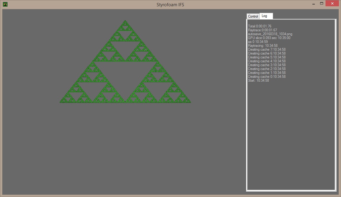
Now you can see much more details of the fractal.
Next we want to use that third dimension.
Open up the first.ifs file again and add a fourth transform at the end of the file.
The position (0,0.1,0) is somewhere near the middle of the other three transforms.
With z of -0.25 added it will roughly form the fourth corner of a tetraeder together with the other three transforms.
xform
scale 0.5,0.5,0.5
translate 0,0.1,-0.25
Save the file, and render again.
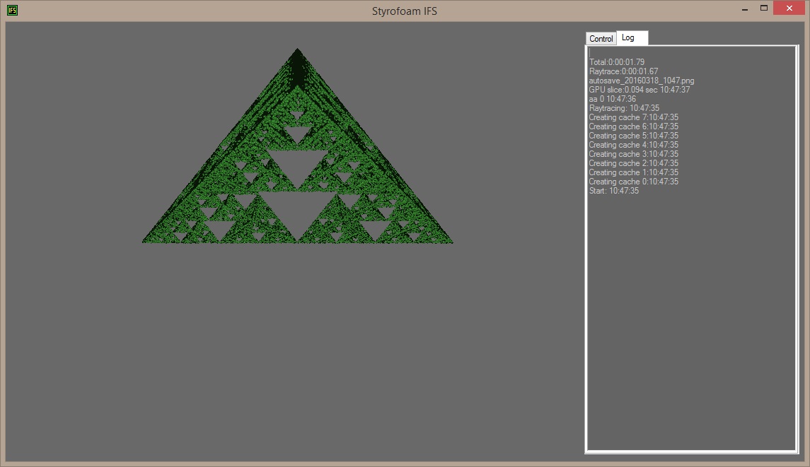
Now the fractal extends into the third dimension.
Adding the third dimension drastically increases the number of iterations needed to look good.
Change the iterations parameter in the first.scene file to 1000000.
iterations 1000000
To look at it from another perspective add the following line to the first.scene file:
camera_position 0,1,-1
Also change the lightsource position to:
lightsource 1,1,-1
And render again.
The camera_position parameter tells the raytracer where it will look from.
By default it will always look towards origo (0,0,0).
The final first.ifs file should look something like this:
xform
scale 0.5
translate 0.2,0,0
xform
scale 0.5
translate -0.2,0,0
xform
scale 0.5
translate 0,0.25,0
xform
scale 0.5,0.5,0.5
translate 0,0.1,-0.25
And the final first.scene file should look something like this:
lightsource 1,1,-1
iterations 1000000
sphere_packing 1200
base_sphere_radius 0.002
camera_position 0,1,-1
The order of the rows in the .ifs file is important within each transform.
The formulas are applied in the order given.
The order of the transforms are not important.
The order of the rows in the .scene file is not important.
Each time you hit the Render IFS button an image will be created in the autosave folder.
Nothing in this folder will be overwritten by Styrofoam IFS.
The filename is printed in the Log and looks something like autosave_20160318_1051.png.
If you open up the autosave directory in the StyrofoamIFS folder you can view the results produced thus far.
With this primer I hope you will be able to understand what is going on when using Styrofoam IFS.
See the manual for more parameters and commands to use.
Play around with the values here and in the examples included.
A final note on units:
Most values here have a generic distance unit. They only start to make sense when put together.
You can think of them as inches or fractal-meters but they really just are generic distances.
The values are choosen as they are here to fit with the default value of the camera position.